 |

 |
||||||||||||||||||||||||||||

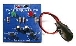
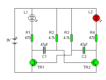
Flashing Lights The circuit diagram of the Flashing Lights is shown below. It consists of two transistors (TR1 & TR2), two electrolytic capacitors (C1 & C2), two lights or LEDs (L1 & L2), and four resistors (R1 to R4). When a 9V battery is connected to the circuit the transistors TR1 and TR2 start to switch on and off in turn causing the LEDs to emit pulses of light. The circuit oscillates. To understand how the circuit oscillates we must consider the voltage variations across the capacitors C1 and C2. Consider the situation just before TR1 switches on. C1 has already charged up to 7 volts through R1. C2 is charging through R3 and when the voltage reaches 0.6 volts TR1 turns on. The collector of TR1 and the positive end of C1 are pulled down to 0 volts which forces the negative end of C1 to -7 volts. This has the immediate effect of switching TR2 off. C1, however, is also connected to +9 volts through R2 and this causes C1 to charge in the opposite direction. The voltage at the negative end of C1 (the base of TR2) therefore starts to fall from -7 volts and rises towards 9 volts. However as soon as the voltage reaches 0.6 volts TR2 switches on and a charged-up C2 turns TR1 off. C2 now charges in the opposite direction through R3. The voltage at the negative end of C2 rises towards 9 volts and turns TR1 on when it reaches 0.6 volts. The circuit is now back in its initial state and the cycle repeats itself. The combination of C1 and R2 determines the time TR2 is switched off, and similarly C2 and R3 determine the time TR1 is off. The values used in the circuit give an on-time (and off-time) of about 1/3 second. This is a rate of 3 flashes per second. 
'Faces' | Construction Sheet | Order Form |
||||||||||||||||||||||||||||
|
||||||||||||||||||||||||||||